What it does
The Coincident Points Tool takes a raw survey x,y,z file as input and searches it for occurrences when the same x,y location is surveyed multiple times. The tool outputs a shapefile that contains the x,y locations, the two different z measurements and the difference between the z values. The difference between the z values can be used as an estimation for uncertainty at theses x, y locations At these locations raster values, such as slope and surface roughness, can be extracted and used to model the relationship between these external parameters and point uncertainty.
For conceptual background about how these coincident points can be used to model uncertainty click here or for a tutorial on how to get started on uncertainty analysis with the output from this tool click here.
Accessing the Tool
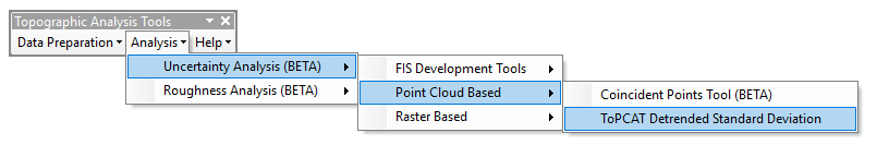
The Coincident Points Tool is located under the Analysis -> Uncertainty Analysis menu under the Point Cloud Based sub menu:
Using the Tool
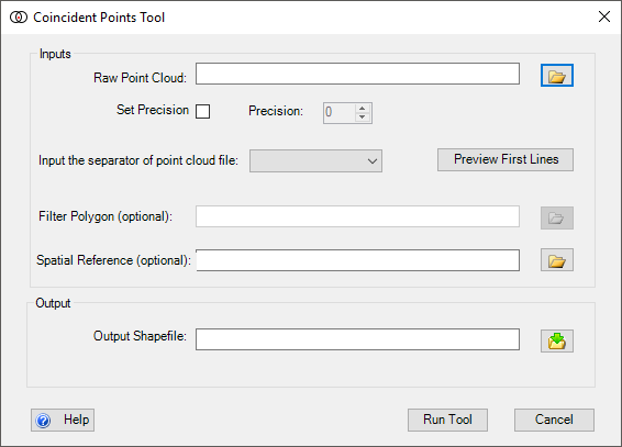
When the Coincident Points Tool is run, the following dialog appears:
The video below describes how to use the Coincident Points Tool:
INPUTS:
The inputs for this tool are:
- Raw Point Cloud
- An ascii text file formatted into columns of x, y, z. Other columns can be present but will not be included in the output shapefile. (headers can be commented out with a
#)
- An ascii text file formatted into columns of x, y, z. Other columns can be present but will not be included in the output shapefile. (headers can be commented out with a
- Set Precision
- By setting this check box the user can select a matching point precision to use other than an exact match of points.
- If a precision other than
0is set then a point does not have to be an exact match to be considered a coincident point. This is mainly used when using highly precise points. For example, if , a1,2or3was specified as the precision an (x,y) pair of points of (1.0001, 1.0000) and (1.0002, 1.0001) would be considered coincident, but if the precision was set to4they wold not be coicicdent.
- Separator (optional)
- The symbol used to separate the x, y, z values. The default is comma
- Spatial Reference (optional)
- Can be in the form of a
*.prjfile or you can load an existing shapefile that contains a spatial reference and that spatial reference will be imported.
- Can be in the form of a
OUTPUTS:
The outputs for the tool are:
- Shapefile or Feature Class
- Contains fields of x, y coordinates for the location, and the two different z fields, and a field that contains the difference between the two z values. Note, output is repeated for every coincident pair found.
 Back to TAT Home